
In the CPU, Mackie uses a part that adapts two motherboard serial port pinouts (COM1 and COM2)
to the single male DB25 port. I replaced this with a
dual DB9 RS232 output ports
plugged into the motherboard and the ports mounted in an unused expansion card slot.
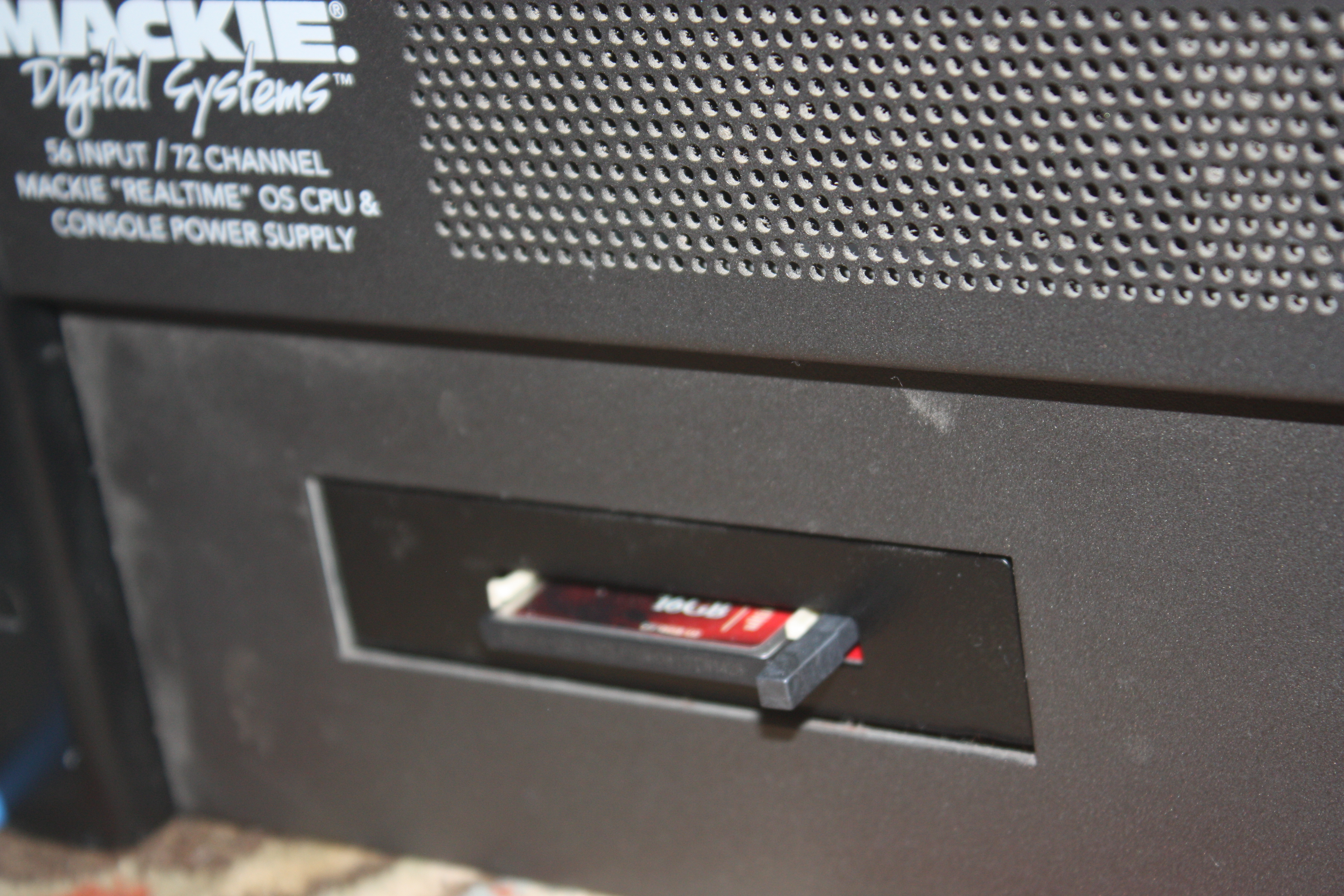 I've replaced the hard drive with an
ejectable IDE flash card adapter
and copied the original hard drive image onto a CF card using
Macrium Reflect Free Edition.
I removed the floopy drive and put the front plate of the flash drive in its place.
This makes it easy to switch back and forth between booting MackieOS (flash card in),
not booting to anything at all (eject the card and the system will stop after the POST
but will still fully power the console, which isn't the case if you remove power from
the motherboard), or booting Linux (insert a different flash card).
I've replaced the hard drive with an
ejectable IDE flash card adapter
and copied the original hard drive image onto a CF card using
Macrium Reflect Free Edition.
I removed the floopy drive and put the front plate of the flash drive in its place.
This makes it easy to switch back and forth between booting MackieOS (flash card in),
not booting to anything at all (eject the card and the system will stop after the POST
but will still fully power the console, which isn't the case if you remove power from
the motherboard), or booting Linux (insert a different flash card).
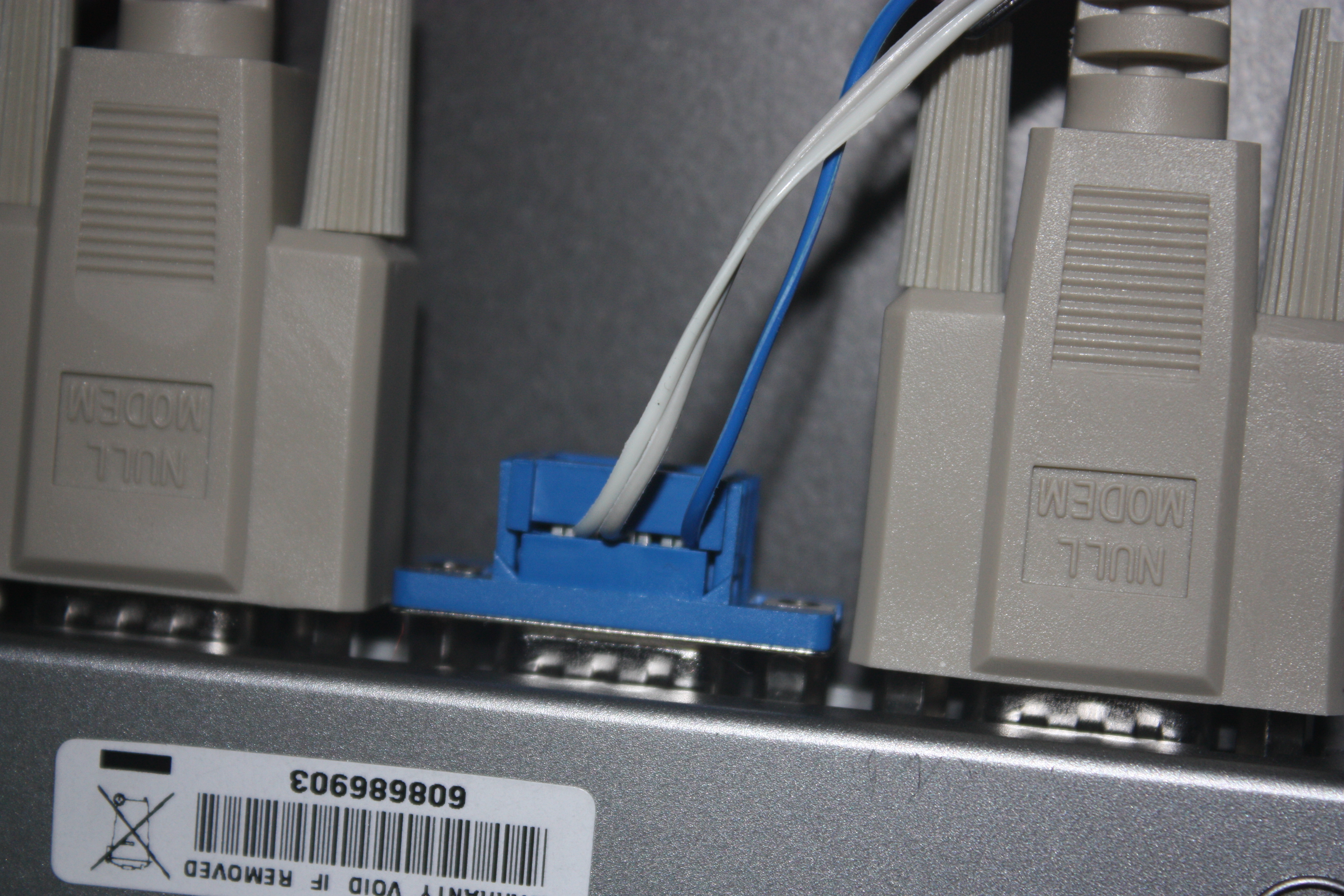
My development/control computer sits in between the CPU and the Console using a
USB quad-RS232 serial port.
I've assigned its ports to COM11 (CPU COM1), COM12 (Console COM1),
COM13 (CPU COM2), and COM14 (Console COM2). The two CPU ports (COM11/COM13) are connected
to the CPU using
null modem RS232 cables
to the corresponding new DB9 RS232 ports on the back
of the CPU. The two Console ports (COM12/COM14) use the custom harness described below
to tether to a stock DB25 cable which runs to the back of the Console.

The power cable is connected as usual from the CPU to the Console.
As best I can tell, the DB25 cable is organized as two sequential RS422 serial lines, but in practice so little of the RS422 protocol is used that it's sufficient to just connect three wires for each (RX, TX, and GROUND). I used ribbon crimb connectors and ribbon cable because they require no soldering and are (if you're careful) reusable.
I built my tether using two DB9 Female ribbon crimp adapters, one DB25 Male ribbon crimp adapter, and some color-coded 10-conductor ribbon cable. This d8b-2-mcu wiki page was very helpful in figuring out how to cross from RS232 to the cable's RS422 wiring.
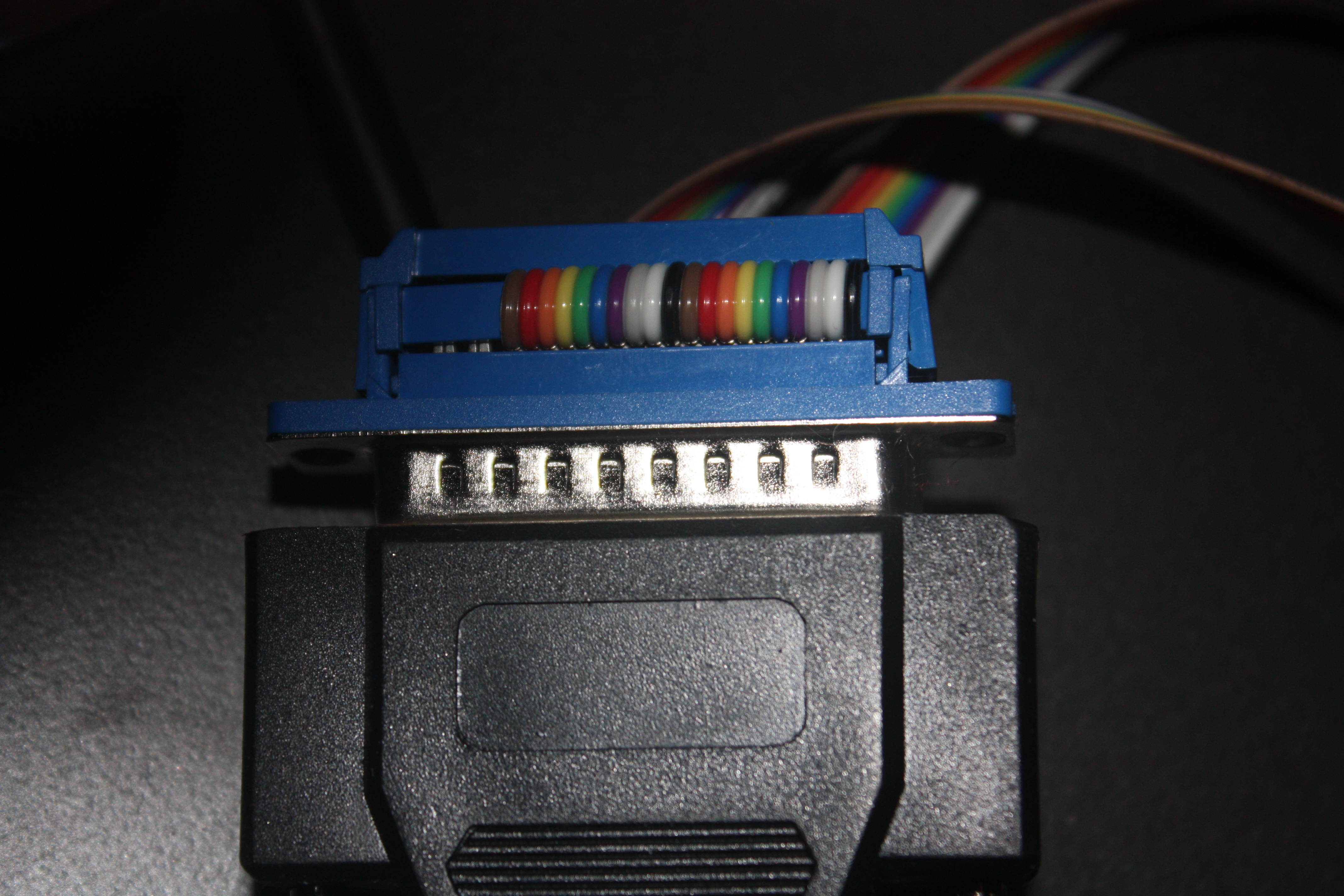 On the DB25 side of the tether, I simply stacked two ribbons,
with the first ribbon's black wire at pin 1
and the second ribbon's black wire at pin 6
(so the ribbons are flush with each other and with the "leftmost" logical side of the connector).
On the DB25 side of the tether, I simply stacked two ribbons,
with the first ribbon's black wire at pin 1
and the second ribbon's black wire at pin 6
(so the ribbons are flush with each other and with the "leftmost" logical side of the connector).
NOTE: Any decent component will have the pin numbers labeled, usually on the contact face -- the part where the male and female connectors interface. Use those numbers to figure out where the wires go. Don't trust your ability to translate between a flat 2D picture and the 3D object in your hands.
 On the DB9 side of the tether, the ribbon connected to the DB25 pin 1 is "COM1"
and the ribbon connected to the DB25 pin 6 is "COM2". They are both connected
to the DB9 using the same pattern:
the second ribbon wire (white) goes to DB9 pin 6,
the third ribbon wire (gray) goes to DB9 pin 2,
and the fifth ribbon wire (blue) goes to DB9 pin 5.
On the DB9 side of the tether, the ribbon connected to the DB25 pin 1 is "COM1"
and the ribbon connected to the DB25 pin 6 is "COM2". They are both connected
to the DB9 using the same pattern:
the second ribbon wire (white) goes to DB9 pin 6,
the third ribbon wire (gray) goes to DB9 pin 2,
and the fifth ribbon wire (blue) goes to DB9 pin 5.
I suspect that a much simpler tether could be built with a dual DB9 RS422 adapter; instead of hand-wiring the DB9 end, you would simply crimp the ribbons directly into the DB9s with each of the black wires at pin 1. I haven't tried this though, so caveat emptor.
I use Eclipse for my day job, so I used it here too.
The code requires the Java 1.8 JRE for the java.time API and a few other niceties.
I used Macrium Reflect Free Edition to snapshot the MackieOS hard drive and build the flash drive images. One irritation is that I was unable to write the flash images using normal USB flash adapters; I had to use the Flash IDE adapter, plugged into an IDE-to-USB adapter.
The source code is in Github: github.com/docbradley/d8b-controller and is currently licensed under LGPL v3.
The code uses the JSSC library to drive the serial port, Google Guava and Apache Commons-IO for utility classes, and the ubiquitous junit for unit testing. Dependencies and build logic are modeled using Maven.
Typeset old-school style using a text editor to write HTML by hand.
Copyright © 2014 Adam D. Bradley. All rights reserved.